Introduction
While auditing the security of embedded devices we often face situations where the firmware of the system under test is either not publicly available or the vendor can’t provide it due to legal issues. Accessing the firmware gives a lot of insight on how the device actually works. Even in assessments, where scope is limited to Web Application Testing only, helpful information can be gathered by having access to the firmware.
This blog post depicts the general approach for retrieving the firmware from such devices by accessing the flash memory chip directly. Please note the provided information in this example is limited to the flash memory chip only, as the tested system cannot be disclosed due to legal constraints.
Accessing the hardware
After opening the housing of an embedded system the initial step is to identify integrated circuits (ICs) that are potential candidates for holding the firmware of the device. As this is highly device-specific the assumption here is that you already have acquired access to the bare PCB.
Identifying the chip
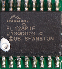
In the following we use the Spansion S25FL128 as an example, which is in broad use for home routers, cable modems and the likes.
RTFM (datasheet)
Specification
General
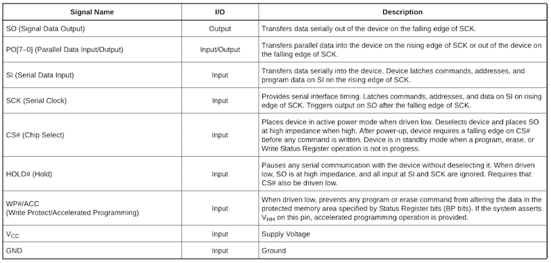
Input and Outputs
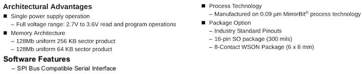
In case of the Spansion S25FL128 the following information can be gathered from the datasheet:
- SPI-like interface
- 16-pin Small Outline package
- can be powered with 3.3 Volts
Knowing the characteristics of the Spansion S25FL128 we are able to proceed with interfacing the chip in order to access and hopefully read its content.
Circuitry
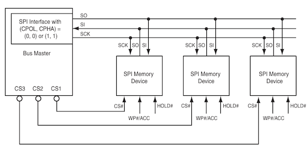
The Spansion S25Fl128 [2] uses Serial Peripheral Interface bus (SPI), which is a synchronous serial communication interface that is used for short distance communication and often found in embedded systems.
SPI Master and Slave
As we are going to read/dump data from the Spansion S25Fl128 we act as bus master with the flash chip being a SPI slave.
In-System Programming
We are going to read the content while the Spansion S25Fl128 is still soldered on the board using a IC test clip such as the Pomona 5252:
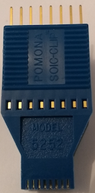
In general it’s recommended to desolder the integrated circuit from the board so that no other component can access it and therefore prevent us from actually dumping the memory. Although we might power other components as well that is a less time-consuming approach and should be tried first.
Pinout (16-pin, Small Outline package)
The following pinout details the bare minimum of mandatory connections (highlighted in red) needed to access the Spansion S25FL128.
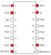
As a rule of thumb pay attention to connecting all pins according to the datasheet and leave no pin floating.
SPI connections
In order to dump the content of the chip, we hookup the aforementioned seven pins to the Spansion S25Fl128 using a Raspberry Pi 3 according to the following table:
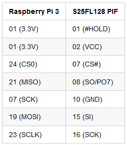
The Raspberry Pi 3 is a cheap system that supports SPI and even
allows us to provide power to the Spansion S25Fl128. Of course you can
make use of other dedicated SPI programming devices as well.
Dumping the firmware image
Flashrom
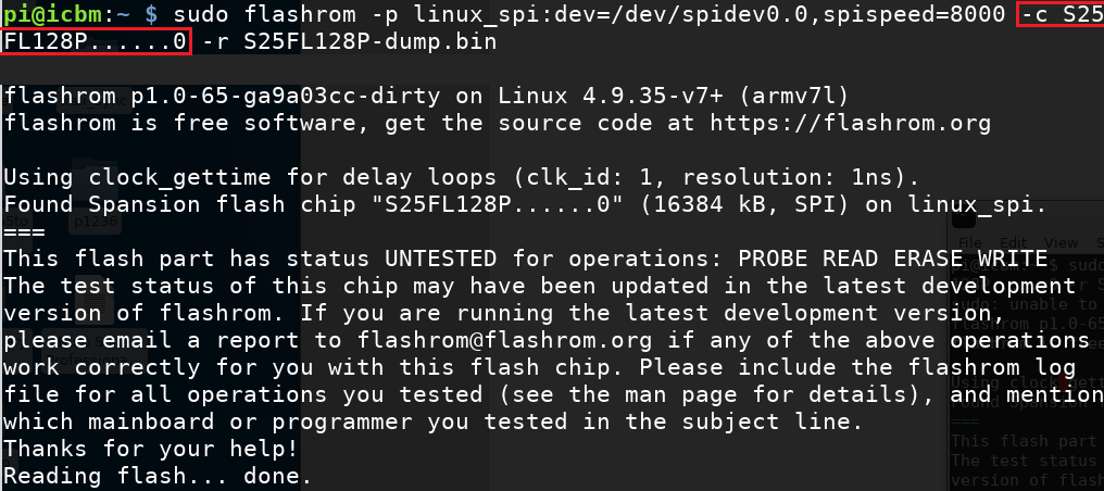
Using flashrom [1] we now try to dump the content of the chip using the SPI device (/dev/spidev0.0) provided by Raspberry Pi 3 as follows:
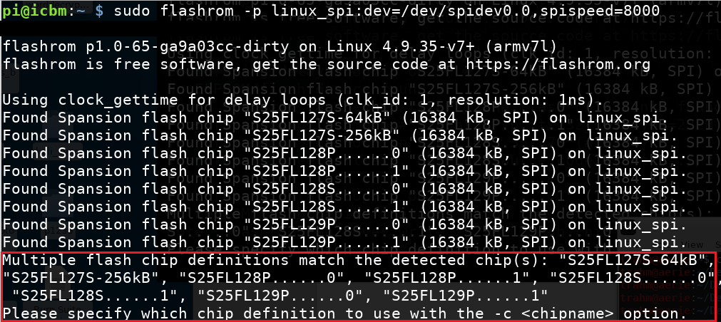
Note that we stated spispeed=8000 explicitly, which sets the SPI speed in kHz and was found to be the maximum speed the Raspberry Pi 3 can handle although your results may vary. This heavily reduces the amount of time needed to dump the entire flash content.
It can be seen from the output above that flashrom fails to identify the integrated circuit unambiguously. As we have identified the specific version in use beforehand we can provide flashrom with the relevant chip identifier using the command-line flag -c:
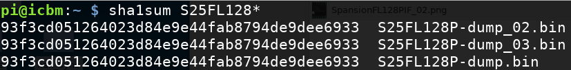
It is highly recommended to dump the image multiple times to verify that the checksum stays the same, which normally indicates a successful read:
Readable Data
A quick look on the acquired firmware image suggests that we have valid data at hand and that this data is unencrypted. Because strings in the dump indicate that uboot is present:

Summary
Resources and Links
[1] https://www.flashrom.org/Flashrom
[2] Spansion S25FL128